Sunday, June 4, 2017

Raspberry Pi Photobooth with Bluetooth Printer and Wii Remote


This project is based on the Raspberry Pi Foundation All Seeing Pi Photobooth project. I wanted to add in the ability to print the photos to a small Bluetooth printer and to email them instead of tweeting them. I also added in the ability to control the Photobooth with a Wii remote. The Wii remote is useful when people want to stand back further from the Photobooth to take a picture.

For the printer I choose to go with an HP Sprocket Printer. This little printer was light, portable and ink-less. The photo is also a sticker, which added to the fun of the Photobooth. While the HP printer normally uses an app on the phone to send pictures to it, it can communicate over Bluetooth with the Raspberry Pi.

The code I tweaked/forked from the All Seeing Pi Photobooth is on my github. The Raspberry Pi foundation does a great job walking through the code and explaining everything. If you want a firm understanding of how the code works I suggest you walk through their tutorial.  In general, the changes/additions I made to the code were:

1) Added in the ability to print the photo
2) Added in the ability to email the photo
3) Added in support for the Wii Remote which includes the ability to go to the previous/next overlay, remove the overlays, take a picture and start a new picture
4) Added in some sound effects
5) Added in some graphics to the GUI
6) Added in some additional filters to overlay on the picture (note googly eyes on the dog below)
7) Uses a kill button to stop the Photobooth since it runs full screen


Materials I used

8.5" x 12" x 4" Wooden Box from Michael's
Buttons
Landzo 7" Touchscreen
PiCamera
Speaker (Optional, nice for camera sound effects)
Optional Button (used to kill the fullscreen Photobooth program)
HP Sprocket Printer (other Bluetooth printers may work, but I haven't tested them)
Chalkboard Paint
Raspberry Pi 3 
Original Wii Remote (NOT THE WII PLUS OR THIRD PARTY REMOTES-IT MAY NOT WORK)

3D Printed Parts

Landzo Touchscreen Case
Simple Pi Camera Mount 
Tripod Mount 


Build the Case

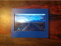
For my case I used a  8.5" x 12" x 4" wooden box from Michael's. It was just the right size to mount the 7" Screen with some room to spare for the buttons and the Raspberry Pi Camera. I designed and printed a case to hold the 7" touch screen and a little mount for the camera. In order to mount the box on a tri-pod, I printed out this tripod mount  and fastened it to the bottom. I also cut a hole in the back so I could access all the parts. Alternatively, you could put the lid for the box in the back and simply cut a little hole for the power to go out. After making all the holes in the box for the screen, buttons and camera I painted the box with black chalkboard paint. I decided to use chalkboard paint so I could change the design depending on the event.


Front with Pi Camera Mount


Attach the Buttons

For this project, I decided to use three buttons. Two buttons are mounted on the front. One cycles through the overlays/picture effects, and the second will take a picture. I attached the Overlay Button to GPIO 23 and the Print Button to GPIO 11. The buttons I chose light up, so each button is also connected to a 5V and Ground Pin. You could also just use a plain style arcade button and forgo the lighting.

I also placed a small reset button in the back and attached it to GPIO 13. This button will kill the Photobooth application since it launches in full screen mode. If you want to hear the sound effects, you can connect a small speaker to the audio jack in the Pi. I love this little speaker I ordered from Amazon. The charge seems to last a long time and does not need any external power to run.


Load the Libraries and Dependencies

My touchscreen came with an Raspbian image pre-configured for the touchscreen, however, any recent version of Raspbian should work. There are several libraries and packages that will need to be installed to get everything working. After running sudo apt-get update, run the following commands to get everything installed:

sudo apt-get install python-imaging-tk
sudo apt-get install python-cwiid


The above commands will add in support for Tkinter (the GUI) and the Wii Remote. Next, the following libraries are needed to support the Bluetooth printing:

sudo apt-get install python-pip python-dev ipython
sudo apt-get install bluetooth libbluetooth-dev
sudo pip install pybluez
sudo apt-get install obexftp

Connect and Test the HP Printer

Now that all the dependencies have been installed, let's connect and test the printer. Turn the printer on and  use the Bluetooth Icon to connect to the printer. If you hover over the device, you will see the MAC address in the dialog box. Write this down as it will be needed later:


After connecting, you may receive an error similar to the following. It's safe to ignore it. Mine seems to work fine regardless:


Now that is has been paired, test the printer to make sure you can send a picture to it. I just took a screenshot of my desktop for a test image to send. Open up a terminal and type in the following (make sure and put in your own MAC address)

obexftp --nopath --noconn --uuid none --bluetooth C4:30:00:00:7E:41 --channel 4 -p screenshot.png


If you have any issues, check out this detailed post by  Matt Richardson, which is where I was able to get this all figured out. If you install the HP Sprocket app on your phone, you can adjust some settings in the printer. By default, the printer turns off after 5 minutes or so. I turned this off so mine remained on the whole time. I also added a strip of Velcro to the underside of the printer to secure it to the top of the box.

Get the Pi-Photobooth scripts 

Make sure you are in the directory /home/pi and clone the repository for Pi-Photobooth:

git clone https://github.com/mdegrazia/Pi-Photobooth

There are four python scripts for the Photobooth program. The main one is photobooth.py. This one runs the Photobooth application and prints the pictures etc. When it launches, it will start up the photobooth_wii.py script as a separate process. The photobooth_wii script is responsible for connecting to the Wii remote. Once connected, it will monitor the buttons pressed and report back to the main script. The third script, overlay_functions.py is used by the photobooth.py script. It contains functions related to the picture overlays. The fourth script, monitor_gpio_buttons.py kills the photbooth application when the button in back is pressed.
 
After the code has downloaded, a couple of lines need to be edited in the photobooth.py file to customize it for your printer and email settings.

nano /home/pi/Pi-Photobooth/photobooth.py

Find the lines at the top of the code under "CHANGE ME", and put in the MAC Address from the printer, your gmail account username and password, and what you would like your email subject line to contain. (The code is currently written to support gmail. You may have to adjust the security settings on your gmail account to send emails from an application)


The  monitor_gpio_buttons.py script needs to start automatically. As mentioned before, this will be responsible for shutting down the Photobooth application when the button on back is pressed. I found this useful because there is no way to exit the Photobooth application when it's running.  To get it to start automatically, edit the crontab file:

sudo crontab -e
@reboot sudo python /home/pi/Pi-Photobooth/monitor_gpio_buttons.py &


After rebooting, start the photobooth.py script through the terminal (dont use ssh, it must be done via the touchscreen)

sudo python /home/pi/Pi-Photobooth/photobooth.py

If all goes well, Photobooth should launch. A sound effect of  will play, meaning that it is looking for a Wii remote. Note - you don't have to use a remote with this, it will work just fine without one too. Push the 1 and 2 buttons simultaneously to sync the Wii remote. Once it's been paired a confirmation message will play and the Wii remote will vibrate.

When the application starts, all the buttons will fire. If necessary, just hit the "New Picture" button to reset everything. Note- the image preview is a GIF, so it will may be a little pixelated. The image that prints out or is emailed will be a full sized png file with better resolution.

Below are how the buttons are configured on the Wii remote:


Note: Do not use a Wii remote Plus, only the original Wii remote

 Finishing Touches

While not necessary, the following are some additional things that can be done.

Add a shortcut on the desktop to start up the Photobooth. To do this, create the file  /home/pi/Desktop/photobooth.desktop with the following contents:

[Desktop Entry]
Version=1.0
Name=PhotoBooth
Comment=PhotoBooth
Exec=sudo python /home/pi/Pi-Photobooth/photobooth.py
Icon=/home/pi/Pi-Photobooth/images/photo-booth.png
Path=/home/pi/
Terminal=false
Type=Application
Categories=Utility;Application;

Customize the touch keyboard to include the '@' symbol to facilitate adding in email addresses. I have a matchbox xml config file included in the repository. Copy the keyboard.xml file provided to the root user profile:

sudo mkdir /root/.matchbox
sudo cp /home/pi/Pi-Photobooth/images/keyboard.xml /root/.matchbox/keyboard.xml


Change the desktop background to a more Photoboothy one. Right click the Desktop, Desktop Preferences, then under Wallpaper browse to /home/pi/Ri-Photobooth/images/photo_booth_background.jpg


You may also want to turn off the screen-saver to keep the screen from turning off.

That's it! For additional fun, check out some of the photobooth props you can buy online or make some yourself.


Tuesday, January 31, 2017

Billy Bass, Alexa and a Raspberry Pi

A friend sent me an email that led to a video of Billy Bass hacked with Alexa. I couldn't stop laughing, and thought it would make a great next project. However, I tried to locate a tutorial associated with the video with no luck. There was a write up on a Teddy Ruxpin/Alexa hack that held the first clue - a sound sensor that was taped onto Alexa that triggered the mouth when Alexa spoke. Some more Googling led to this video by Maker Project Lab and subsequent comments, which had some helpful links, including that of the internal mechanics of Billy Bass. There was also somewhat of a challenge issued to do this project on that Maker video, so... challenge accepted :) . Although there have been other hacks done, this is my hack which is a little bit different than what I have seen so far.

I really wanted to use a Raspberry Pi and an instance of Alexa installed on the Raspberry Pi rather than commandeer my Echo Dot. My project ended up using: 1) A Raspberry Pi with an Adafruit Motor HAT to drive the mouth and head, 2) Alexa installed on the Raspberry Pi, 3) the speaker inside Billy Bass for Alexa and 4) the battery pack inside Billy Bass to power both the Billy Bass Speaker and Motors. A sound sensor taped down on the speaker inside Billy Bass provided the triggers to move the mouth and head when Alexa spoke. Everything but the Pi fit neatly into Billy Bass and I drilled a hole in the back to thread the wires out to the Raspberry Pi. I also remixed/made a 3D printed case to house the Raspberry Pi and Motor HAT.


I wrote a short python script that reads the sound sensor that is taped onto the speaker. When the sound goes above a certain threshold, the head will lift, and the mouth will move. It moves in time with the words pretty well if the threshold it adjusted correctly. It should be pretty easy to add in some code for the tail as well, but I was OK with just these movements for now.

All the code can be downloaded from my Github, and the parts and walk though are detailed below. Here is a video of the completed project:


Materials
Big Mouth Billy Bass (check ebay, Amazon or a local thrift store)
Adafruit Motor Hat  
Adafruit Microphone Amplifier MAX4466 AKA sound sensor (Amazon or Adafruit)
MCP3800 8-Channel 10-Bit ADC with XPI
Adafruit Class D Audio Amplifier MAX 9744 (Amazon or Adafruit )
Playstation Eye Microphone
Raspberry Pi (Amazon or Adafruit)
male/male audio/headphone type cable 

Although I got a lot of supplies from Adafruit, similar items are available from other outlets and manufacturers - I like to support Adafruit because of all their great tutorials and project ideas. This also assumes that the Raspberry Pi has already been loaded up with the latest version of Raspbian (not the light version as a browser is needed to activate Alexa) and that all the normal accessories are available for it - sd card, power, wifi, etc. An audio jack is needed so a Pi Zero won't work unless some mods are made to it.

Roadmap
Gut Billy Bass
Hook up the Motors
Hook up the Billy Bass Speaker
Hook up the Sound Sensor
Install Alexa
Grab the Billy Bass python script
Make Billy Bass pretty again


Gutting Billy Bass
 This tutorial was helpful for me in gutting Billy Bass. Basically, I unscrewed the back and cut all the wires. As I cut, I made sure I left enough wire in case I wanted to reuse them. There was also a little circuit board screwed down on the inside that I cut all the wires from and discarded. The stuff  I  re-purposed for this project were the motors, speakers, battery pack and the motion sensor on/off switch in the back (but not the actual motion sensor). I had two motors in my Billy Bass. One motor was used to drive the mouth, and the other motor was used to drive the head and tail, depending on which way the motor is ran.  If you have a Billy Bass with three motors (head, tail and mouth) this project should still work with a couple tweaks.

Billy Bass Front Inside


Billy Bass Back Inside
Hook up the Motors
I had an Adafruit Motor HAT from a previous project so I decided to use it to drive the motors. The Motor HAT fits right on top of the Raspberry Pi and can drive up to four DC motors. Adafruit has a nice Python library to drive the motors, and since Python is my programming language of choice, this made it an easy choice for me.
  • Followed the Adafruit tutorial on assembling the Motor HAT and installing the Python library
  • Connected the Head/Tail motor to the Motor 1 terminal
  • Connected the Mouth motor to the Motor 2 terminal


I decided to use the Billy Bass battery pack and the motion sensor on/off switch to power the Motor HAT. See below for how I wired it up:


If it's wired up correctly, when the motion sensor switch is on, the Motor HAT LED will light up green like the picture above.

I wrote a little script, MotorCheck.py to test the motors once they were hooked up. The head and mouth should move when the script runs. If the tail does, it simply requires switching the wires in Motor HAT terminal 1.

Hook up the Speaker
I decided to install Alexa on the Raspberry Pi rather than use my Echo Dot. Alexa needs a speaker so you can hear her talking. Since the Raspberry Pi doesn't have a speaker, I decided to re-purpose the Billy Bass speaker for Alexa's voice. In order to do this, I used a Class D Audio Amplifier - Max9744 from Adafruit. This let me connect the headphone jack from the Rasbperry Pi and route the audio to the raw speaker inside Billy Bass. Although there were other amplifiers available,  I choose the Max9744 because it was small, and can take 5 Volts, which the internal Billy Bass battery pack is capable of supplying.
  • Followed the Adafruit instructions on how to assemble the Max9744
  • Connect the 2.5mm audio jack to the Raspberry Pi
     

Next I connected the power terminal on the MAX9744 to the switch and battery pack inside Billy Bass. In order to do this, I had to solder two additional wires on the on/off switch:


Hook up the Sounds Sensor
I needed a way to "trigger" the mouth and head when Alexa talked. As I mentioned before,  I saw a picture from this Teddy Ruxpin write up that showed a sensor taped onto the top of an Echo. After seeing this, I wanted to write a python script that monitored a sensor taped down to the Billy Bass speaker. When it detected Alexa talking, the python script would turn on the mouth and head motors for Billy Bass.

The first sound sensor I tried was this red one from Atomic Market. I choose it because it had a Digital Out pin which would be relatively easy to hook up to one of the Raspberry Pi's GPIO pins. I could not seem to get the sensor dialed in correctly. It was either extremely sensitive and triggered all the time, or nothing at all. I could not get it to work as I wanted. Maybe you'll have more luck?

After fussing with that I decided to try the Adafruit Microphone Amplifier MAX4466 which ended up working beautifully. The downside was that it required more wiring then a simple Digital Out pin, but, in my opinion was worth  the extra effort as the mouth movement ended up syncing nicely with Alexa. To convert the analog signal for the Raspberry Pi, I used an MCP3800   chip and followed the wiring diagram I found here.The chip uses SPI, so I had to enable SPI through the raspi-config interface:


I wrote a python script, SensorCheck.py that will test the sensor by outputting the sound values. The sensor is not meant to hear noise on the other side of the room, which makes it perfect for responding to noise coming just from the Billy Bass speaker which it will be taped onto.


Install Alexa
Installing Alexa on the Raspberry Pi was super easy and free. I followed the detailed instructions on the Amazon Alexa github page. The micro USB microphone suggested on the Github page was OK, but I kinda had to shout to get Alexa to hear me. I also had to trouble shoot it to get it to work by editing the asoundrc file. I had a  Playstation Eye  microphone laying around that I thought worked better. Although it's a bit bigger and bulkier, it worked right off the bat, and I didn't have to shout. Once Alexa was up and running , the next step was to get the Billy Bass mouth to sync with her voice.


Billy Bass Python Script
The BillyBass.py python script is responsible for monitoring the sound sensor, moving the mouth and lifting the head when it hears Alexa speak. The sensitivity level can by adjusted in the script by changing the variable SENSITIVITY.   If the mouth seems to lag or not move, the sensitivity may need to be adjusted up (IE - moved from 900 to 1000). If the mouth is moving like crazy, the sensitivity needs to be adjusted down (IE - from 1000 to 800). I found that I had to play around with this until I found just the right setting to sync the words and mouth movement.

It was a little tricky getting the head to pop up and stay up as the head needs be lifted when Alexa is quite and listening to the user's request. I set a timeout feature that will raise the head when it first hears sound (IE, the trigger word "Alexa"), then starts counting the number of loops while it's quite. After its been quite for a certain amount of time (loops), the head lowers. This value can be adjusted with the variable HEAD_PAUSE. If it's too low, the head will move back down while you are still talking to the fish - to high and his head will remain up for a long time after Alexa is done talking. Once again, trial and error helped find the correct value.

On a side note, after I got everything put back into Billy Bass and was testing it,  the fish head kept  bouncing back and forth against the back board even though nothing was being said. I kept thinking to myself "Quit hitting yourself, Quit hitting yourself". It turned out that each time the head lowered it knocked the board hard enough to register a noise on the sound sensor causing the head to pop back up again. This was fixed easily enough in the code by having the script sleep for a few seconds while the head lowered before checking for sensor values.

Make Billy Bass Pretty Again
When everything was working as wanted, I put all the components except for the Raspberry Pi back into the Billy Bass housing. I drilled a hole to thread the wires through that needed to be plugged into the Pi and the switch on the back can be used to turn the motors and speakers on/off.

Now I can ask Billy Bass to add items to my shopping list, tell me jokes and add items to my shopping list. Who wouldn't want that?


Next Steps/Outstanding Issues
I would like to get the script to start and stop based on the Alexa wake word. This will make it less likely to respond when it hears ambient noise or voices.

I noticed some feedback from the motors over the speakers. Switching the motors to their own power supply fixes this. I probably need to do some better wiring to stop the feedback.